Geometry nodes in Blender
What are Geometry Nodes?
Geometry nodes are a great approach to non-destructive modeling. This means that at any part in the modeling process we can toggle and adjust any modifications we've made before.
Non-destructive modeling
If, for example, we want to bevel an edge, we can do so with Ctrl+B and apply the changes, but then the only way to revert them is to go back with Ctrl+Z, undoing all that we've done after. If we use a bevel modifier instead, we can toggle it on or off whenever we want. Blender has many useful modifiers theat change the shape of, destroy, or add geometry. With Geometry Nodes we can create something like custom modifiers.
Changing geometry with nodes
There are many things that wouldn't be possible without Geometry Nodes. For example, let's try to create a bar chart with random values.
We start with a singular bar. It'll be a simple cube, with its pivot point moved down, so that when we scale it, it only goes up.
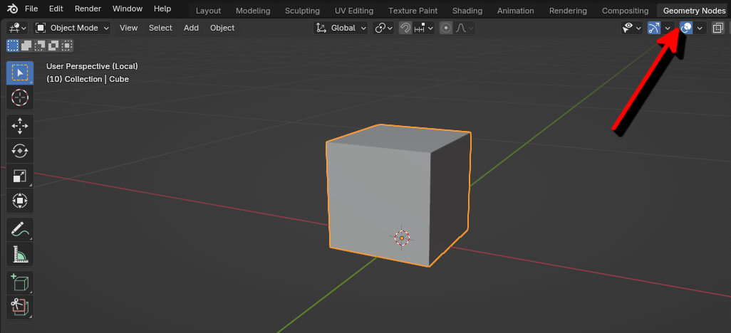
Then, let's switch to the Geometry Nodes workspace and create a new group with he "New" button. Here we'll add our nodes to create a bar chart.
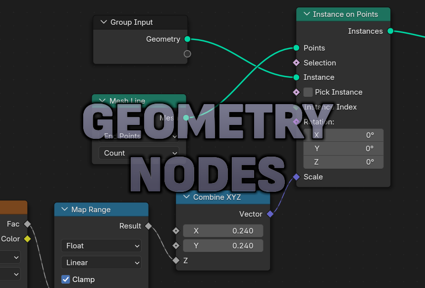
Because we want the bars next to eachother in a line, we'll use the Mesh Line node. Under "Mode", select "End Points" to set a start and end point. We'll set the number of points to 40. Then we'll create an instance on each of those points, so we'll have 40 bars. For that let's use the Instance on Points node. To give them a random height, we can use a Noise Texture node, but before connecting it to the Scale input, we'll pass it through the Z coordinate of the Combine XYZ node (so that it only controls the height. To increase height fluctuations add a Map Range node and change the min and max values. And finally, to make the diagram move to the side, let's increase the X coordinate of the Noise texture vector over time. Use the Position node (to get the current position) and a Vector Math node (to increase it), connecting them to the Vector input of the Noise texture. In the field for the X coordinate of the Vector Math node create a driver by typing "#frame / 50", which will set the X coordinate to the current frame of the animation divided by 50 (to slow it down). That will add motion to the bars.
Our node tree should look like so:

And the result like so:
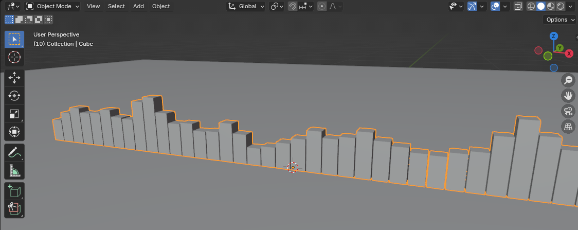
That's how we can create a bar diagram with Geometry Nodes. The best part is that we can visualize what our node group does. That's a very basic example, there are much more advanced things we could do, especially after the addition of Node Tools in Blender 4.0, which allow us to use the current selection and the mouse position in 3D space.
After we add some colourful materials, set the contrast and add some composition effects, we get a nice result: